By C. Chris Peters
Just as visual artists use clay to create sculpture that we can see, composers
and sound designers use various electronic signal generating and signal modifying
devices to shape music and sound effects we can hear.
The art of sound sculpting started in the 1960’s with the appearance of the analog synthesizers using the concept of voltage control. Sound sculpting, often associated with early electronic music, is a form of performance art where an artist or group of artists use synthesizers, turntables, tape loops and amplified acoustic objects to create a continuous sonic environment. During the 1960’s the analog synthesizer, often the sonic “star” of these shows, offered performing artists greatest access to the strangest sounds because of its real-time access to operating its parameters.
The analog synthesizer is really an offshoot of the analog computer in its concept and design. It contains oscillator, filter, and amplifier circuits that are designed to imitate the sonic characteristic functions of musical instruments. The original concept of the synthesizer was to create new sounds that could not otherwise be created by acoustic instruments. Despite this, both analog and digital synthesizers are used more extensively by composers and sound designers to imitate familiar acoustic instruments.
The biggest apparent drawback with using early analog synthesizers in performance situations is that they didn't’t have a way to recall previously created instrument sounds. It wasn't’t until the 1970’s when microprocessors became less expensive and more available did analog synthesizer builders incorporate facilities to allow the instruments to memorize their sound settings. This made commercially available instruments analog/digital hybrids. Adding digital circuitry also changed the way these instruments were programmed by musicians. Preprogrammed algorithms known as presets were used more and more and determined the instrument’s sound, making them less useful for genuine sound sculpting.
Analog versus Digital Instrumentation
In the presence of today’s digital technology, it is hard to imagine things analog. In brief comparison, analog flows where digital steps. Analog uses thresholds where digital uses exact numbers. Analog is various shades of gray where digital is black or white.
An analog computer can be thought of as a machine that continuously runs an equation. It uses sets variables instead of data. The output is dependent upon how the values are set and when those variables change their values. Meters are often used to display the output of analog computers.
A digital computer can be thought of as machine that translates information that follows a set of predetermined rules. Information (or data) must be brought to the microprocessor, where the microprocessor, following the set of predetermined rules (or programs) transforms the provided information into new information. Once the transformation process is complete, the microprocessor moves on to its next transformation task. The newly transformed information can be printed or viewed on a screen as output.
In the grand scheme of things, analog computer systems are not as flexible as digital systems because of the finite number of controllable variables they use. Analog systems do not use programs. Their functions (equivalent to operations in the digital world) are hardwired and optimized to do very specific things. Digital systems use programs to change the behavior of their operations making them more flexible and are better used as general purpose machines to solve a much wider variety of problems.
The Rebirth of the Control Panel
During the 1960s the analog synthesizer consisted of a collection of oscillators, amplifiers, filters, and some means to control them. These collections of components were manually controlled by turning knobs, flipping switches and “patched” or hardwired together to make sounds. The early synthesizers had large control panels, were expensive and very unpredictable. They were also solo instruments, like brass and woodwind instruments, capable of producing one sound.
During the late 1970s manufacturers of electronic musical instruments included computer technology in their instruments as the prices of microprocessors became inexpensive. These hybrid analog/digital instruments preserved that “warm” analog sound, they took away much of the control of the instruments parameters from the performer but offered polyphony and memory to recall control panel settings. They also offered limited polyphony, capable of producing several sounds at once like guitars and keyboards.
During the 1980s totally digital instruments became much less expensive to build and buy. These instruments were much cheaper to build, much smaller and very reliable. Most of the early digital instruments used microprocessors to generate and control their sounds. The musical instrument digital interface (MIDI) was developed as an easy way to communicate between microprocessors in digital synthesizers. Liquid crystal displays (LCDs) were used to view preset names and control functions. Only a few control knobs are needed to navigate through the many options listed in menu-like fashion. The totally digital instruments worked from preset programs and were difficult to program in real-time. They also have a different or “cold” sound than the analog instruments. Their price and the fact that you could play them without knowing how to program them made the hybrid instruments economically unviable.
During the early 1990s, digital signal processors (DSPs) were developed for use in the telecommunications industry. Musical instrument manufacturers used them to “model” the sounds of the much missed original analog instruments of the 1960s and 70s. They made digital synthesizers that were designed to sound and feel like analog synthesizers. More knobs were added for real-time control replacing the menu system of programming. The modeled analog instruments took advantage of more advanced and reliable electronic manufacturing techniques.
During the late 1990s personal computers (PCs) became cheaper, faster, and more commonly used by musicians. DSP technology became incorporated into the PCs ability to generate sounds. Software synthesizers or applications that mimic the functions of synthesizers became very popular. Software developers created GUI (Graphic User Interface) screens that actually look like the control panels of the older analog synthesizers made during the 1970’s. These software based synthesizer applications cost a fraction of what their hardware counterparts did minus the cost of the computer they are running on. Many software instruments are available free if you download them from the Internet.
The Properties of Sound
The three basic properties of sound are pitch, timbre, and loudness.
Pitch is a musical term for scientific term “frequency” which is the rate of vibrations per a period of time. Frequency is measured in cycles per second. The unit of measurement of cycles per second is called Hertz (Hz).Low frequencies produce low pitched sounds. A tuba produces a low pitched sound. High frequencies produce high pitched sounds. A piccolo produces a high pitched sound. Humans can hear frequencies between 20Hz to 20 KHz.
Timbre is the quality or special characteristic of a sound. Timbre is a word that is used to describe the shape or harmonic structure of a sound’s waveform. Using an oscilloscope to monitor the waveform shapes of a recorder, a trumpet, and a flute playing at the same pitch and loudness we can generalize the following: a recorder displays a square shaped waveform structure; a trumpet displays a saw-tooth shaped waveform structure; and a flute displays and sine waveform structure.
Loudness is also referred to as volume. Loudness is a musical for the amount of dynamic level (volume) or force a sound has as it reaches your ears. A sound with a loudness measuring 20 to 50 dB has little force to our ears. A sound with a loudness measuring 80 to 100 dB has a lot of force to our ears. A sound with loudness greater than 115 dB will damage our ears.
The Basic Architecture of an Analog Synthesizer
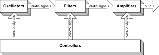
Analog synthesizers are modular in their configuration. Each module is responsible for specific functions. These functions are broken down into three types of categories: audio signal generation, audio signal modification, and control signal generation.
• Oscillators generate audio.
• Filters modify signal quality.
• Amplifiers modify signal strengths.
• Keyboards and Modulators control signal level amounts.

Module Descriptions
In 1975 ARP, a manufacturer of analog synthesizers produced a set of battery operated modules specifically designed for classroom use. The following are brief descriptions and front panel diagrams of ARP's MSL modules.
Oscillators -VCO
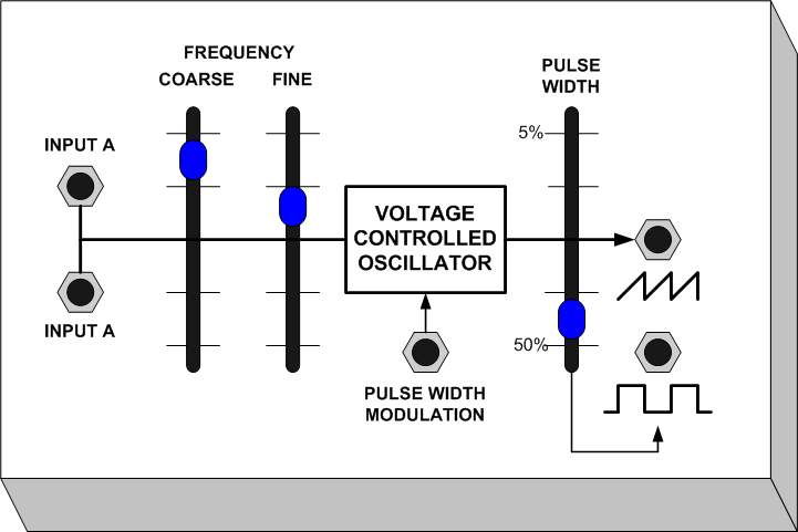
The Voltage Controlled Oscillator’s function is to provide periodic waveform signals (tone) in saw-tooth and rectangle waveform shapes.
VCO Features:
• Two control signal inputs used for controlling the VCO’s frequency
from another device.
• Course frequency adjustment for sweeping through frequency ranges.
• Fine frequency adjustment for sweeping through small frequency ranges.
• Pulse-width modulation input use for controlling the shape of the rectangle
wave shape from another device.
• Pulse-width % adjustment used to manually reshape the rectangle wave
shape.
• Saw-tooth waveform audio signal output
• Rectangle waveform audio signal output
Filters - VCF
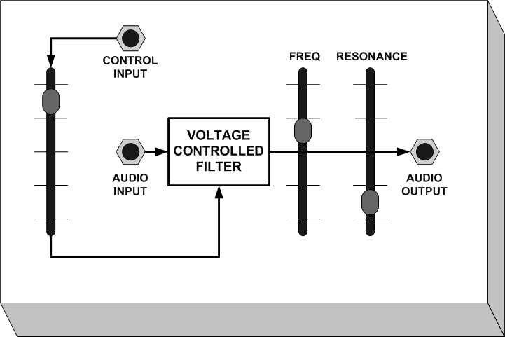
The Voltage Controlled Filter’s function is to reshape the timbre of incoming audio signals. This is done by filtering out harmonic frequencies in determined ranges. Resonant low-pass filters are the most common types of filters found in analog synthesizers.
Note: When a resonant frequency is set all the way up, it will feedback or self-oscillate producing a sine waveform, making filters viable oscillators.
VCF Features:
• Manual control for adjusting the level of a control signal from another
device
• Control signal input allows the VCF to be controlled from another device
• Audio input provides an input for audio signals to be processed by the
VCF
• Freq (frequency) control for adjusting the frequency of audio signals
up to which the filter attenuates (will not let pass).
• Resonance control adjusts the amount of feedback. When in self oscillation,
the Freq control can be used to set the frequency of the filter’s oscillation.
• Audio output provides an output for processed audio signals from the
VCF
Amplifiers - VCA
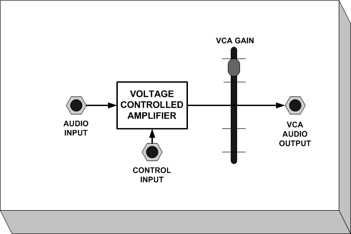
The Voltage Controlled Amplifier’s function is to provide dynamic (over time) control the loudness of incoming audio signals. Voltage controlled amplifiers in most analog synthesizers are really voltage controlled attenuators. Attenuation is the opposite of amplifying.
VCA Features:
• Audio input provides an input for audio signals to be processed by the
VCA.
• Control input allows the VCA to be controlled by another device
• VCA Gain manual control adjusts the level of attenuation the VCA has
on incoming audio signals.
• VCA output provides an output for processed audio signals from the VCA
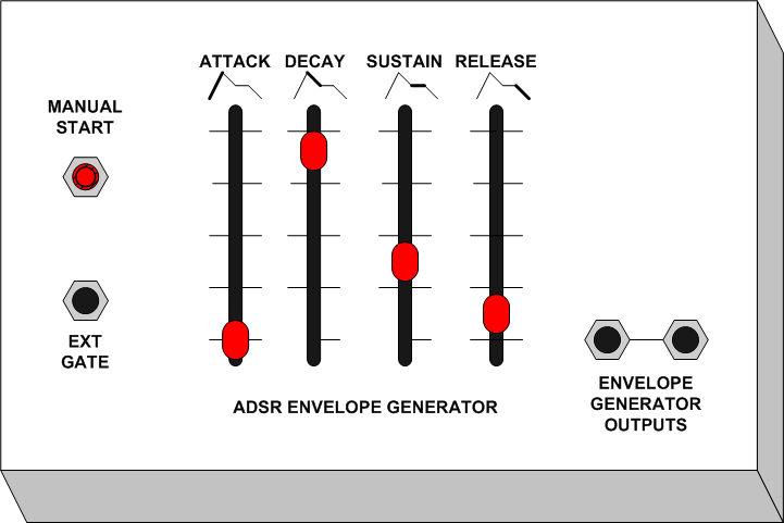
Envelope Generators - ADSR
The envelope generator controller or ADSR generates signals used to create changes over time. These changes over time are called events. There are four basic event stages: attack time, decay time, sustain level, and release time. Envelope generators require gate voltages of about ten volts to function. As long as there is a gate voltage present the envelope generator will go through all four stages of an envelope event once.
ADSR Features:
• Manual Start button when pushed initiates the generation of an envelope
event.
• Ext gate input accepts gate voltages from other devices (such as sequencers
and keyboard controllers).
• Attack control adjusts the rate (amount of time) of the attack lag or
how suddenly the event starts.
• Decay control adjusts the rate (amount of time) from the initial attack
down to the level of sustain.
• Sustain control adjusts the level of sustain at which an event will
stay until there is less than 10 volts of gate signal.
• Release control adjusts the rate (amount of time) from the sustain level
down to the end of the event.
• Two envelope generator outputs generate control signals to control other
devices.
Mixers
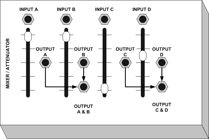
Mixers are devices that combine the output signals of several devices into one or two channels. They are also used to balance audio signal levels.
Mixer / Attenuator Features:
• Four inputs (A, B, C, and D)
• Four controls to adjust the levels of the inputs
• Four outputs (A, B, C, and D)
• Two combined outputs (A&B, C&D)
Noise Generators
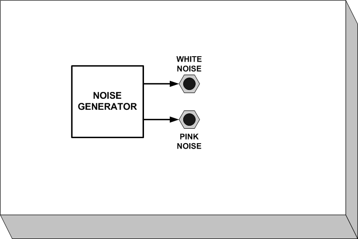
Noise signal generators produce random (non-periodic) audio signals we humans perceive as noise. White noise is high frequency noise. It sounds like hissing. Pink noise is low frequency noise. It sounds like rumbling. Noise generators can also be used as control signals in situations were a periodic control (like pulse waves from clocking devices) are not wanted.
Features:
• White noise audio signal output
• Pink noise audio signal output
Ring Modulators
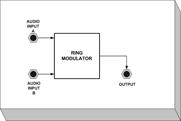
Ring modulators require two input signals to process sound. The ring modulator combines these signals and outputs the sum and the difference that sounds to create complex ( and often dissonant) sounds. When two signals from separate oscillators are fed into the ring modulator at roughly the same frequency, nothing is really heard. As one of the oscillators is detuned to a slightly higher or lower frequency, the dissonant harmonics are accentuated and a clangorous metallic ringing is produced.
Features:
• Two audio inputs
• Audio output
Sample and Hold
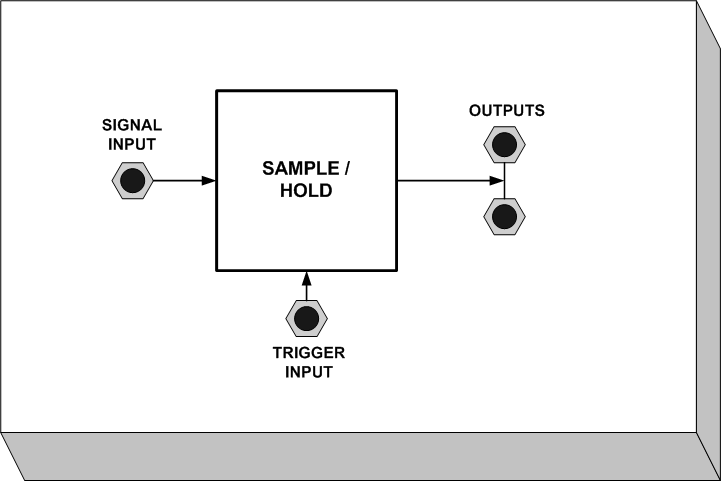
The sample and hold is a two input device. It requires a trigger control signal input and audio signal input to function. The trigger control signal can be obtained from a random signal like noise or a clock signal (a very narrow pulse waveform running at a sub-audio speed). Sample and hold selects a voltage level based on information from the incoming audio signal and outputs that voltage level until it is retriggered by the control signal to select a new level.
Features:
• Signal input from an audio source
• Trigger input from a noise generator or clock VCO
• Two control signal outputs use to control VCOs, VCFs and VCAs
Multiple
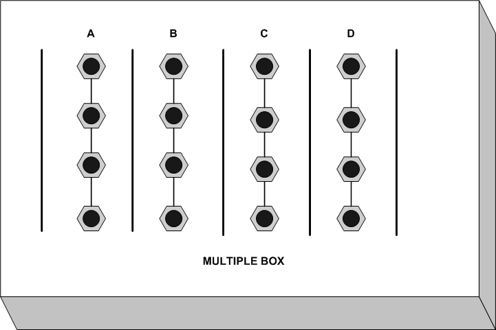
The multiple contains four parallel fields or jacks connected together. This permits multiple connections to modules that have only one control input.
Features:
Four parallel fields with four inputs each.
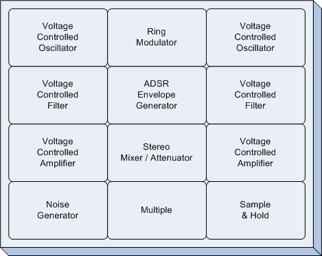
The following is a typical Synthesizer hardware configuration for sound sculpting consisting of twelve ARP MSL modules. Patch cords are used to make all the connections between modules. Control signal and audio signal levels are compatible. This means that no damage will occur if a control signal output is connected to an audio signal input. All synthesizer modules are powered with either one or two 9 volt batteries. Fresh batteries will run a module for about six hours of continuous use.
The Stereo Mixer / Attenuator module must be connected to a musical instrument amplifier or stereo receiver in order to hear sounds. Sound producing devices such as Voltage Controlled Oscillators, Voltage Controlled Filters in self oscillation and Noise Generators output audio signals at full strength and can possibly damage sound systems if plugged directly into them. Turn down the monitoring amplifier before connecting these devices.
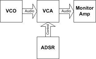
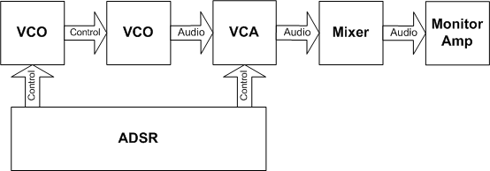
In a classroom situation, students learn to use the analog synthesizer modules by using the using the following suggested configurations. Note that arrows are used for patch cord connections and help indicate the direction of flow and type of signal.
Patch 1 - Basic sound

Patch 2 - VCA controlling loudness of a VCO

Patch 3 - VCO loudness using the ADSR envelope generator to control a VCA
Patch 4 - VCO filtered using an ADSR controlled VCF with loudness manually controlled by a VCA
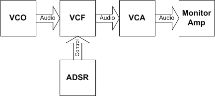
Patch 5 - Two VCOs processed by a Ring Modulator using an ADSR controlled VCA for loudness
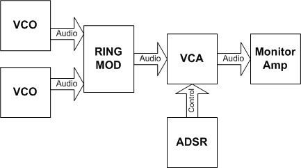
Patch 6 - Surf noise, noise generator using an ADSR controlled VCA for loudness
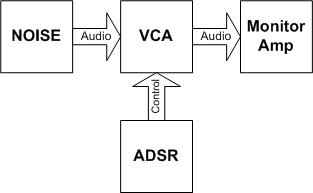
Patch 7 - Sample & Hold Pitch (note: the left most VCO is usually operating in a low frequency range)
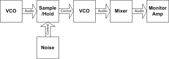
Patch 8 - Sample & Hold Filter (note: the left most VCO is usually operating in a low frequency range)
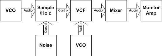
Patch 9 - ADSR envelope controls the pitch of a VCO using a mixer to manually control loudness

Patch 10 - Frequency Modulation
© C. Chris Peters 2010 - cchrispeters.com